This document will walk you through the procedure of connecting to your USB-microDig with the Editor
application. For this walkthrough, you will need:
- USB-microDig digitizer
- Turn sensor (or any other sensor)
Necessary Software
As of version 3.5 of the Editor, you will need the following software installed to connect with the USB-microDig:
- The Editor
- BlueMIDI (included with Editor installer)
- Virtual COM port driver (included with Editor installer, also available here.
- Virtual MIDI port software, such as loopMIDI.
Installing the Editor application
You can find the latest Editor
here.
Extract the .zip file to a folder, and then click on Setup.exe.
Follow the instructions in the installer. BlueMIDI will also be installed.
Installing and Using LoopMIDI to create a virtual MIDI port
The editor lists several virtual MIDI port options. This document will use LoopMIDI, which you can download
here.
Run the installer, and then double click to launch loopMIDI. It will appear on the bottom of the screen, in the system tray.
-
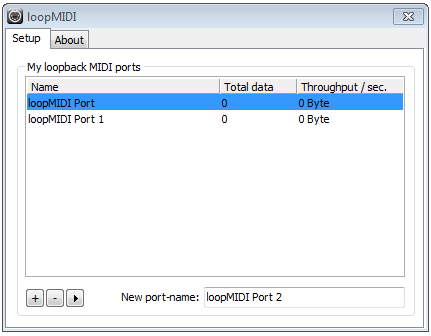
Start LoopMIDI. Using the "+" button, add two ports, 1 for "IN" and one for "OUT". The window should look like this:
Connecting to the USB-microDig with BlueMIDI
BlueMIDI is used to connect the USB-microDig and the virtual MIDI port set up in LoopMIDI.
- Open BlueMIDI and select the COM port of your USB-microDig and click "Connect". You should see the following:
Connecting to the USB-microDig with the Editor
The Editor allows you to configure the USB-microDig so that sensor data is processed and turned
into MIDI messages. While the USB-microDig is connected to the
Editor, these messages are sent to other applications by using virtual MIDI ports.
Plug in the USB-microDig to power it on.
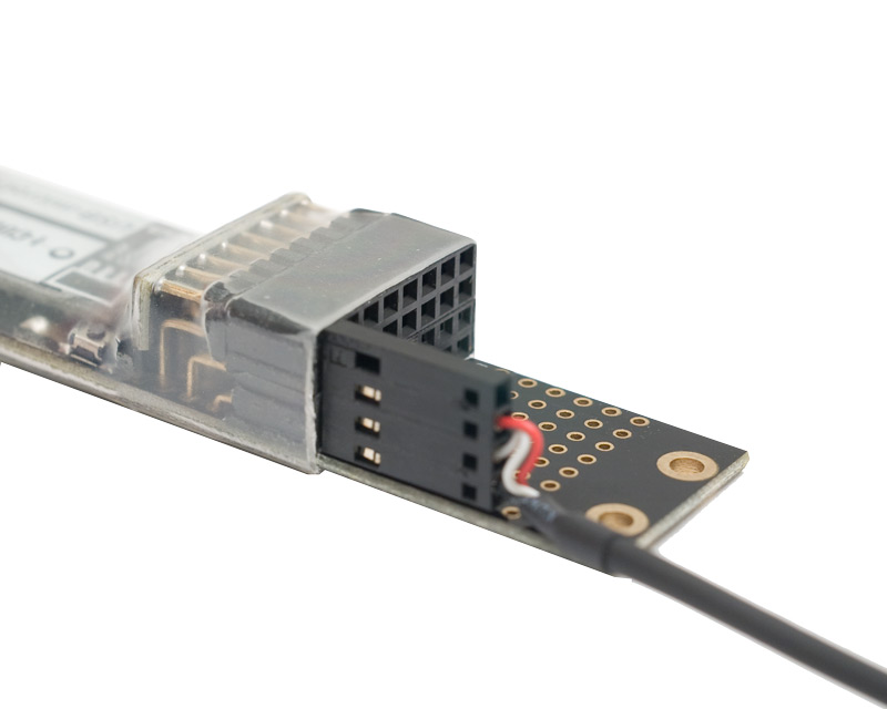
Connect the Turn sensor (or any other sensor) to input #1 of the
USB-microDig.
Make sure the sensor is connected as shown below, with the red wire on top
and the black wire on the bottom.
Launch the I-CubeX Editor.
In the "Choose interface" pull-down menu, choose "MIDI". If you don't see the loopMIDI ports, click "Add MIDI Interface"
When adding the interface, make sure "In" and "Out" match what you selected in loopMIDI.
If the MIDI port doesn't appear, check that loopMIDI is running. It can be found on the bottom of the screen, in the system tray.
Select the entry in the table and click "Open".
Wait until the "Connected" check box next to the table entry is
checked and click on the "edit" radio button.
Click on "Test connection". You should see the "in" and "out" lights
blinking on the USB-microDig, indicating that the messages are getting there from the Editor.
Select "New" from the configuration selection window. Clicking on "File"
would let you load a configuration from a file, and "Digitizer" would load the current
configuration from the Digitizer
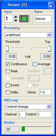
Add a sensor window. (Configure > Add Sensor)
Click "On" in the sensor window.
Rotate the Turn sensor knob and verify that the green bar in the
bottom of the sensor window moves between values 0 and 127.
You've now connected to the USB-microDig with the Editor, and configured it such that sensor input #1 is
turned on and sending data. Since it's in standalone mode by default, the
microDig will retain its sensor configuration even after being powered off. To use it with other
MIDI-enabled software or hardware, you can either connect to the USB-microDig with the Editor, or with
the BlueMIDI application, which acts a bridge between the virtual serial port and MIDI.


 LinkedIn group