This document will walk you through the procedure of connecting to your Digitizer with the Editor application.
For this walkthrough, you will need:
- Digitizer and included 9V power supply
- MIDI interface
- Turn sensor (or any other sensor)
Installing the Editor application
You can find the latest editor
here.
Open the .zip file, and move the Editor folder into to your Applications folder.
Connecting to the Digitizer with the Editor
The editor allows you to configure the Digitizer so that
sensor data is processed and turned into MIDI messages.
You can then send these messages to other software applications.
You'll need to use the editor at least once to configure your Digitizer, after that the Digitizer retains these
settings - even after powering off - until you next change them in the editor.
Example:
turn on sensor input 1, set the sampling interval to 50ms, make sensor input 1 send "Control Change"
MIDI messages.
Connect the Digitizer to the 7.5V power supply to power it on.
Connect the Digitizer's MIDI cables to your MIDI interface. Make sure that the red cable marked
"Out" connects to the "In" port of your MIDI interface, and that the black cable marked "In" connects
to the "Out" of your MIDI interface.
Normally on MIDI hardware, "In" means "MIDI messages come in here" and "out"
means "MIDI messages leave from here". On certain interfaces, this convention is not followed,
which makes things confusing.
Connect the Turn sensor (or any other sensor) to input #1 of the
Digitizer.
Make sure the sensor is connected as shown below, with the red wire on top
and the black wire on the bottom.
Launch the I-CubeX editor.
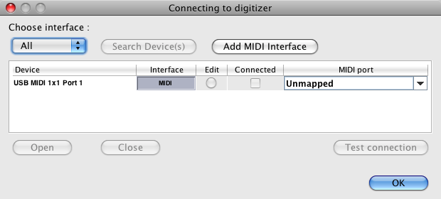
In the "Choose interface" pull-down menu, choose MIDI (or All).
You should see your MIDI interface listed in the table.
Note that for some MIDI interfaces where the "in" and "out" ports are named
differently, you'll need to add a custom MIDI in/out port by clicking on "Add MIDI interface".
Select the "in" and "out" ports from the pull-down menus, and then click "OK". Once added, use that
custom port to connect to your MIDI interface.
If you don't see your MIDI interface at all, make sure
your driver is properly installed.
Select the entry in the table and click "Open"
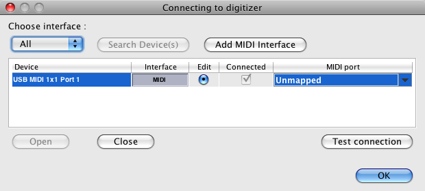
Wait until the "Connected" check box next to the table entry is
checked and click on the "edit" radio button.
Click on "Test connection". You should see the lights blinking on the MIDI
interface, indicating that the messages are getting there from the editor.
If you don't see the
lights blink, it means the messages aren't getting to your interface from the editor. Check that
the "edit" radiobutton is clicked, and that your MIDI interface drivers are properly installed.
If you see the lights blink on your MIDI interface but not on your Digitizer, check that the cables
are connected to the right ports.
Select "New" from the configuration selection window. Clicking on "File"
would let you load a configuration from a file, and "Digitizer" would load the current
configuration from the Digitizer.
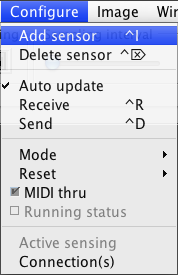
Add a sensor window. (Configure > Add Sensor)
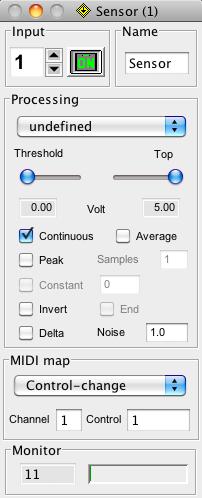
Click "On" in the sensor window.
Rotate the Turn sensor knob and verify that the green bar in the
bottom of the sensor window moves between values 0 and 127. You can also change what type of MIDI
message you'd like to send from this sensor input.
You've now connected to the Digitizer with the editor, and configured it such that sensor input #1 is
turned on and sending data. Since it's in standalone mode by default, the
Digitizer will retain its sensor configuration even after being powered off. To use it with other
MIDI-enabled software or hardware, you no longer need to use the editor, unless you want to change the
settings.


 LinkedIn group