These are instructions to assemble the wiring connector that comes with the DIY sensors. You can also follow these instructions to wire any 5V sensor that that output an analog output signal.
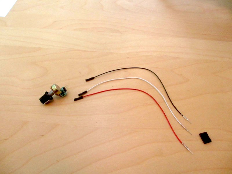
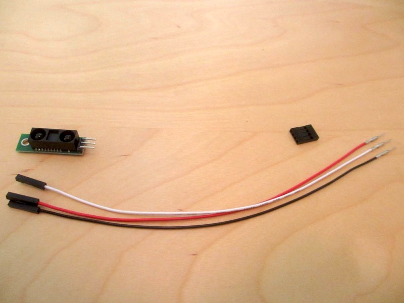
The following components are included for each sensor to be assembled:
- Red wire (for power)
- White wire (for signal)
- Black wire (for ground)
- Connector plug
- Sensor module
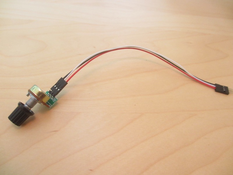
First, gather up all the required parts for a sensor. Following shows the potentiometer sensor:
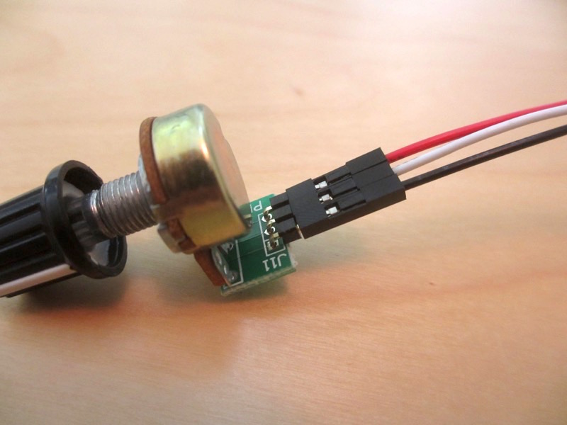
Next, connect the female ends of the wires to the male headers on the sensor. The red and black wires can be switched – you would just get the reverse signals as you turn the knob in the same direction. However, make sure the white wire is in the middle!
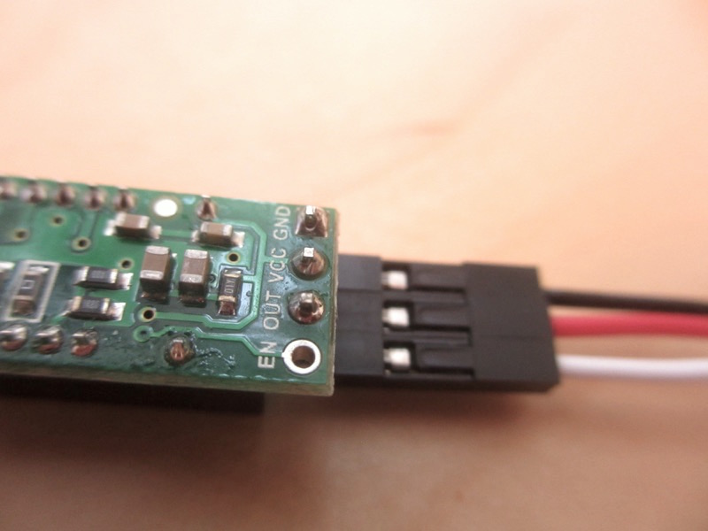
On the connector side, make sure the black wire is at the bottom part of the connector, white in the middle, and red on top:
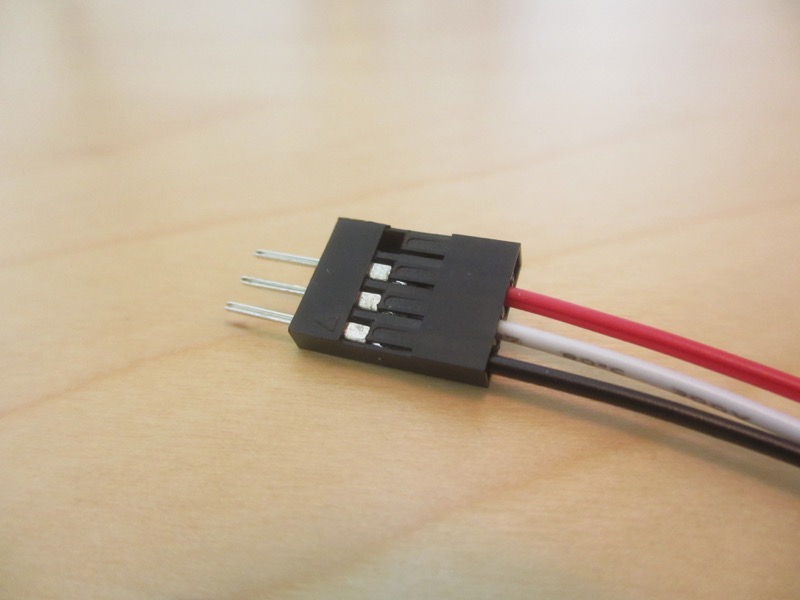
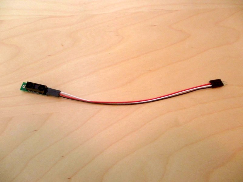
This is what you should end up with:
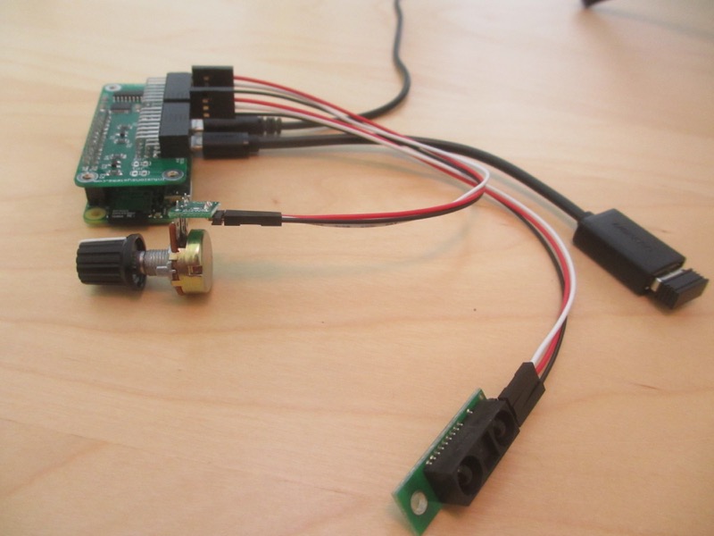
Now do the same for the rest of your sensor modules, and you’re good to go. For example, following shows the assembly of the IR distance sensor:
Note here that the signal order on the sensor is different, and the OUT (signal) wire is at the end. Make sure your wires line up accordingly!
Now you’re ready to use them with the PiShield! Following shows the two sensors connected to a PiShield on a Raspberry Pi Zero: