Difference between revisions of "EditorX Sensor Input"
| Line 52: | Line 52: | ||
Please refer to the [[http://icubex.com/support/firmware-72-usbmicrodig.pdf firmware 7.2]] documentation for details about these presets. | Please refer to the [[http://icubex.com/support/firmware-72-usbmicrodig.pdf firmware 7.2]] documentation for details about these presets. | ||
| − | [[File: | + | [[File:sensor_magnetic3d.png]] [[File:sensor_moist.png]] [[File:sensor_movealong.png]] [[File:sensor_movearound.png]] [[File:sensor_orient3d.png]] |
| Line 63: | Line 63: | ||
*Peak / Dip End notification | *Peak / Dip End notification | ||
*Smoothing (EditorX 7.2) or Averaging (EditorX 7.1) | *Smoothing (EditorX 7.2) or Averaging (EditorX 7.1) | ||
| − | * | + | *Difference calculation |
*Constant output | *Constant output | ||
*Inversion | *Inversion | ||
| − | The Continuous output method checks whether the sensor value has changed more than the Noise value before it is transmitted as a MIDI message. The Noise value can be set separately in steps of 0.5 when the MIDI message transmits sensor input values as 7-bit values (all MIDI messages except | + | A sensor input will only process values if either the Continuous or Peak method is enabled, or both. When multiple processing methods are selected, the double arrows on the right of the Processing menu will be coloured white against a black background. |
| + | |||
| + | The Continuous output method checks whether the sensor value has changed more than the Noise value before it is transmitted as a MIDI message. The Noise value can be set separately in steps of 0.5 when the MIDI message transmits sensor input values as 7-bit values (all MIDI messages except PitchBend), and in steps of 4 when the MIDI message transmits sensor input values as 14-bit values (pitchbend messages). Setting the Noise value to zero (only available in EditorX 7.2) results in all sensor values being output. | ||
[[File: processing_continuous.png]] | [[File: processing_continuous.png]] | ||
| Line 79: | Line 81: | ||
If the Peak / Dip End notification method is enabled, a MIDI message with value 0 is output if the sensor value reaches the Min value after a peak has been detected. If the Inversion method is enabled a MIDI message with value 127 (or 16383 in the case of pitchbend messages) is output is the sensor value reaches the Max value after a dip has been detected. | If the Peak / Dip End notification method is enabled, a MIDI message with value 0 is output if the sensor value reaches the Min value after a peak has been detected. If the Inversion method is enabled a MIDI message with value 127 (or 16383 in the case of pitchbend messages) is output is the sensor value reaches the Max value after a dip has been detected. | ||
| − | The Smoothing method (EditorX 7.2) applies an [[https://en.wikipedia.org/wiki/Exponential_smoothing exponential moving average]] filter to the sensor values. The smoothing factor can be set separately, and a higher value increases the smoothing. The Averaging method (EditorX 7.1) applies a [[https://en.wikipedia.org/wiki/Moving_average simple moving average]] filter to the sensor values. The number of samples used to calculate the average can be set separately, and a higher number increases the smoothing. The advantage of the exponential smoothing average compared to the simple moving average is that the former results in less latency while providing a smoother output. | + | The Smoothing method (EditorX 7.2) applies an [[https://en.wikipedia.org/wiki/Exponential_smoothing exponential moving average]] filter to the sensor values. The smoothing factor can be set separately, and a higher value increases the smoothing. The Averaging method (EditorX 7.1) applies a [[https://en.wikipedia.org/wiki/Moving_average simple moving average]] filter to the sensor values. The number of samples used to calculate the average can be set separately, and a higher number increases the smoothing. The advantage of the exponential smoothing average compared to the simple moving average is that the former results in less latency while providing a smoother output. The Smoothing or Averaging method will only be active when either the Continuous or Peak method is enabled, or both. |
[[File: processing_smooth.png]] | [[File: processing_smooth.png]] | ||
| − | The | + | The Difference method outputs the difference between the current and the previous sensor values. The Difference method will only be active when either the Continuous or Peak method is enabled, or both. |
[[File: processing_continuous-difference.png]] [[File: processing_peak-difference.png]] | [[File: processing_continuous-difference.png]] [[File: processing_peak-difference.png]] | ||
| − | The Constant output method allows for the output of the same value each time a peak or dip has been detected. The constant value can be set separately in steps of 16. | + | The Constant output method allows for the output of the same value each time a peak or dip has been detected. The constant value can be set separately in steps of 16. The Constant method will only be active when the Peak method is enabled. |
[[File: processing_constant.png]] | [[File: processing_constant.png]] | ||
| − | The Inversion method inverts the range of the sensor input, ie. a higher sensor value results in a lower output value. This method can also be realized by selecting the [[EditorX_Lookup_Tables | Lookup Table]] method in the analog sensor methods. | + | The Inversion method inverts the range of the sensor input, ie. a higher sensor value results in a lower output value. This method can also be realized by selecting the [[EditorX_Lookup_Tables | Lookup Table]] method in the analog sensor methods. The Inversion method will only be active when either the Continuous or Peak method is enabled, or both. |
[[File: processing_continuous-inversion.png]] [[File: processing_peak-inversion.png]] | [[File: processing_continuous-inversion.png]] [[File: processing_peak-inversion.png]] | ||
Revision as of 04:53, 1 November 2015
The Sensor Input section configures a single sensor input of the digitizer.
Analog/Digital
The analog/digital feature only applies to EditorX 7.2.
Sensors are either analog or digital. Analog sensors output a single value that is captured by the digitizer using its analog to digital converter, after which a number of algorithms can be applied to process the sensor value and output it as a MIDI message. Digital sensors convert analog value(s) in the sensor itself and output a serial binary data stream using the I2C protocol that is received by the digitizer, which then can apply a number of algorithms to process the sensor values and output them as MIDI messages.
When selecting Analog, a number of conversion methods will be made available that may be applied in conjunction with processing methods. When selecting Digital, a number of sensor presets can be selected, applicable to the corresponding I-CubeX sensors.
Analog Sensors
For analog sensors the following conversion methods are available:
- Lookup table
- Absolute value
- Time duration
- Frequency
- Absolute value, then frequency
A lookup table takes the sensor value as the index for a table and then outputs the value stored at that index. This method is useful for linearizing the response curve of a sensor, such as the ReachClose, ReachFar and all Touch sensors.
File:Conversion lookup-table.png
The absolute value method subtracts an offset value of the sensor value and if the result is negative, changes the sign of the value so that the output is always positive.This method is useful for sensors whose value at rest, ie. when the sensor is not stimulated, is not zero but varies around a value, such as the BendMicro/Mini/Short, BioVolt and GForce3D.
File:Conversion absolute-value.png
The time duration method counts the milliseconds between a peak (or dip) and the following peak (or dip), if no Peak / Dip End notification processing method is enabled. If Peak / Dip End notification is enabled, the time duration method counts the time between a peak and its end (ie. the time the value drops below the threshold set for peak detection). The range of the time duration is 1 - 16383 ms. The time duration unit can be set separately, and setting it to 1 means the time duration is output in milliseconds, setting it to 100 means the time duration is output in 10ths of a second. This method has many applications, such as measuring the time between taps on a Touch sensor, the time a hand was held over a ReachClose sensor or the time between two activations of a MoveOn sensor.
The frequency method operates like the time duration method but outputs a frequency instead of the time duration. The frequency unit can be set separately, and setting it to 1 means the frequency is output in Hertz (Hz), setting to 60 means the frequency is output as beats per minute (BPM). This method has many applications, such as measuring the BPM of taps on a Touch sensor, or the frequency of breaking a SeeLaser-Red beam pointed at a Flash sensor.
File:Conversion frequency-Hz.png File:Conversion frequency-BPM.png
The "absolute value, then frequency" method combines the absolute value method with the frequency method. This method is useful for capturing beats per minute (BPM) when using a BioVolt as a heartbeat sensor.
Digital Sensors
The following digital sensor presets are available:
- Magnetic3D
- Moist
- MoveAlong
- MoveAround
- Orient3D
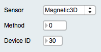
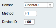
Please refer to the [firmware 7.2] documentation for details about these presets.
Processing
The following processing methods are available:
- Continuous output
- Peak / Dip detection
- Peak / Dip End notification
- Smoothing (EditorX 7.2) or Averaging (EditorX 7.1)
- Difference calculation
- Constant output
- Inversion
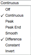
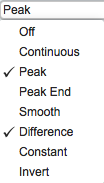
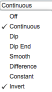
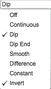
A sensor input will only process values if either the Continuous or Peak method is enabled, or both. When multiple processing methods are selected, the double arrows on the right of the Processing menu will be coloured white against a black background.
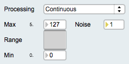
The Continuous output method checks whether the sensor value has changed more than the Noise value before it is transmitted as a MIDI message. The Noise value can be set separately in steps of 0.5 when the MIDI message transmits sensor input values as 7-bit values (all MIDI messages except PitchBend), and in steps of 4 when the MIDI message transmits sensor input values as 14-bit values (pitchbend messages). Setting the Noise value to zero (only available in EditorX 7.2) results in all sensor values being output.
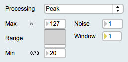
The Peak / Dip detection method starts searching for a peak or dip if the sensor value equals or crosses the Min threshold (ie. the Min value of the Range slider below the Processing menu). As long as each subsequent sensor value is greater than the previous value, no value is transmitted as a MIDI message. As soon as the sensor value is smaller or equal as the previous value a MIDI message is output where the sensor value is scaled between the Min and Max value of the Range. After the peak is detected and output, no new peak will be searched until the sensor value is equal or lower than the Min threshold. If the Inversion method is enabled, the search for a dip is started if the sensor value is lower than the Max value of the Range slider. A MIDI message is output as soon as the sensor value is equal or smaller than the Min value of the Range slider. No new dip will be searched until the sensor value is equal or higher than the Max value. The number of samples that are analyzed before establishing whether the sensor value is equal or smaller (peak) or larger (dip) than the previous sensor value can be set separately. Setting the number of samples higher than 1 allows for sub-peaks, eg. due to noise, to be filtered out.
If the Peak / Dip End notification method is enabled, a MIDI message with value 0 is output if the sensor value reaches the Min value after a peak has been detected. If the Inversion method is enabled a MIDI message with value 127 (or 16383 in the case of pitchbend messages) is output is the sensor value reaches the Max value after a dip has been detected.
The Smoothing method (EditorX 7.2) applies an [exponential moving average] filter to the sensor values. The smoothing factor can be set separately, and a higher value increases the smoothing. The Averaging method (EditorX 7.1) applies a [simple moving average] filter to the sensor values. The number of samples used to calculate the average can be set separately, and a higher number increases the smoothing. The advantage of the exponential smoothing average compared to the simple moving average is that the former results in less latency while providing a smoother output. The Smoothing or Averaging method will only be active when either the Continuous or Peak method is enabled, or both.
The Difference method outputs the difference between the current and the previous sensor values. The Difference method will only be active when either the Continuous or Peak method is enabled, or both.
The Constant output method allows for the output of the same value each time a peak or dip has been detected. The constant value can be set separately in steps of 16. The Constant method will only be active when the Peak method is enabled.
The Inversion method inverts the range of the sensor input, ie. a higher sensor value results in a lower output value. This method can also be realized by selecting the Lookup Table method in the analog sensor methods. The Inversion method will only be active when either the Continuous or Peak method is enabled, or both.
Please refer to the [firmware 7.2] documentation for more information about processing methods.
MIDI Message
The MIDI Message settings configure the digitizer to output MIDI messages with the sensor value. The following MIDI messages can be selected:
- NoteOff
- NoteOn
- KeyPressure
- ControlChange
- ProgramChange
- AfterTouch
- PitchBend
If the sensor input is configured to process values continuously as well as detect peaks or dips and their ending, the peak or dip and their ending are sent in the form of the MIDI message selected but additional MIDI key-pressure messages are sent to transmit the sensor value after the peak or dip is detected and until their end is detected.


