|
|
| (36 intermediate revisions by the same user not shown) |
| Line 7: |
Line 7: |
| | Commands can be sent while the digitizer is in host or standalone mode, with sensor data being output in either mode. | | Commands can be sent while the digitizer is in host or standalone mode, with sensor data being output in either mode. |
| | | | |
| − | The command format has the general form "<outlet> <command> <value>", where <outlet> is a value between 0 and 32, with 0 signifying the command is system-wide, and where <value> can be a float as well as an integer and is not required for all commands. | + | The command format has the general form "<outlet> <command> <value>", where <outlet> is a value between 0 and 32, and where <value> can be a float as well as an integer and is not required for all commands. If the outlet value is 0 it signifies the command applies system-wide, and not just for a specific input. All other values specified for <outlet> refer to the iCube outlet with the same number, ie. not the sensor input since the data outlet could have been connected to a sensor input with a different number. Multiple commands can be entered as one message, ie. without commas between each command. The outlet parameter "<outlet>" can be substituted by "<outlet1> - <outlet2>" to specify all outlets from <outlet1> to <outlet2>, which range can be ascending or descending. |
| | | | |
| | If a command has aliases they are listed following the command, in brackets and separated by commas. | | If a command has aliases they are listed following the command, in brackets and separated by commas. |
| Line 13: |
Line 13: |
| | Commands that in turn send commands as System Exclusive MIDI messages to the digitizer refer to the firmware command in capitals. More information about the command can be found in the applicable firmware section on this support wiki. | | Commands that in turn send commands as System Exclusive MIDI messages to the digitizer refer to the firmware command in capitals. More information about the command can be found in the applicable firmware section on this support wiki. |
| | | | |
| − | For each command (sent or received) messages are output via the message outlet that provide confirmation or report an error. These messages can be used for eg. debugging or the sequential timing of communication with the digitizer. | + | For each command (sent or received) messages are output via the message outlet that provides confirmation or reports an error. These messages can be used for eg. debugging or the sequential timing of communication with the digitizer. |
| | | | |
| | | | |
| − | <b>System-wide commands</b>
| |
| | | | |
| | + | <b>Arguments</b> |
| | | | |
| − | <u>version</u> (0 version) | + | iCube takes 4 optional arguments. Arguments are entered after the name "iCube" with spaces between each argument. If no arguments are given, the iCube object will default to 8 outlets (virtual outputs) and the MIDI System Exclusive Device ID will default to 0. The first argument indicates the number of outlets. If the first argument is not in the range [0..32] an error message will be shown in the Max window as well as output via the message outlet. The second argument indicates the MIDI System Exclusive Device ID (which must match the System Exclusive Device ID of a connected digitizer in order to work). If only one argument is provided or if the second argument is less than zero, the System Exclusive Device ID defaults to 0 and an error message will be shown in the Max window as well as output via the message outlet. The third argument (a string with at most 99 characters) can be used to identify messages from the iCube object instance in the Max window. It can be left empty by typing " " (a space with two double quotes). The fourth argument specifies the digitizer firmware (where eg. firmware v7.5 is entered as "75"). If no firmware is specified, iCube will assume default digitizer specs (maximum 32 inputs, maximum 12-bit resolution, minimum 0 ms sample interval and System Exclusive Device ID 0) and will try to identify the digitizer upon receipt of the first MIDI byte. See also the <u>version</u> command. If the fourth argument is -1 the iCube object will execute the sync command upon instantiation. |
| | | | |
| − | Reports the iCube version and, if available, digitizer version in the Max window.
| |
| | | | |
| | | | |
| − | <u>reset</u> (0 reset) | + | <b>Instantiation</b> |
| | | | |
| − | Initializes the iCube data structure as per the <u>init</u> command and sends a RESET command to the digitizer.
| + | Upon instantiation, the oCube is initialized as follows: |
| − | | |
| − | | |
| − | <u>init</u> (0 init)
| |
| − | | |
| − | Initializes the iCube data structure to the default settings as specified below.
| |
| | | | |
| | System-wide: | | System-wide: |
| Line 42: |
Line 36: |
| | Input-specific: | | Input-specific: |
| | | | |
| − | *connect: connect each outlet to the sensor input with the same number | + | *connect: each outlet is connected to the sensor input with the same number |
| | *stream: 0, ie. off | | *stream: 0, ie. off |
| | *inmin: 0 (sensor input minimum voltage) | | *inmin: 0 (sensor input minimum voltage) |
| Line 58: |
Line 52: |
| | *function: 0, ie. analog sensor with voltage output | | *function: 0, ie. analog sensor with voltage output |
| | *method: 0 | | *method: 0 |
| − |
| |
| − |
| |
| − | <u>sync</u> (0 sync)
| |
| − |
| |
| − | Retrieves all the configuration information from the digitizer and stores it in the iCube data structure.
| |
| − |
| |
| − |
| |
| − | <u>digid <value></u> (setdigid <value>, 0 digid <value>)
| |
| − |
| |
| − | Sends a SET ID command to the digitizer to set the digitizer's System Exclusive ID to <value>.
| |
| − |
| |
| − |
| |
| − | <u>id <value></u> (0 id <value>)
| |
| − |
| |
| − | Sets the iCube to respond to and send System Exclusive messages with the System Exclusive ID equal to <value>.
| |
| − |
| |
| − |
| |
| − | <u>host</u> (0 host, 0 hostmode)
| |
| − |
| |
| − | Sends a SET MODE command to the digitizer to set it to host mode.
| |
| − |
| |
| − |
| |
| − | <u>standalone</u> (0 standalone, 0 standalonemode)
| |
| − |
| |
| − | Sends a SET MODE command to the digitizer to set it to standalone mode.
| |
| − |
| |
| − |
| |
| − | <u>mode <value></u> (0 mode <value>)
| |
| − |
| |
| − | Sends a SET MODE command to the digitizer to set to its mode specified by <value>.
| |
| − |
| |
| − |
| |
| − | <u>interval <value></u> (0 interval <value>)
| |
| − |
| |
| − | Sends an INTERVAL command to the digitizer to set its sampling interval to <value> ms.
| |
| − |
| |
| − |
| |
| − | <u>rate <value></u> (0 rate <value>)
| |
| − |
| |
| − | Sends an INTERVAL command to the digitizer to set its sampling rate to <value> Hz.
| |
| − |
| |
| − |
| |
| − | <u>mute <value></u> (0 mute <value>)
| |
| − |
| |
| − | Sends an SET MUTE command to the digitizer to set its mute status to <value> (0 is off, 1 is on).
| |
| − |
| |
| − |
| |
| − | <u>report</u> (0 report, print, 0 print)
| |
| − |
| |
| − | Reports all the available data stored in the iCube data structure in the Max window.
| |
| − |
| |
| − |
| |
| − | <u>verbose <value></u> (0 verbose)
| |
| − |
| |
| − | Sets what kind of messages are printed in the Max window, according to <value>:
| |
| − |
| |
| − | * 0: no messages
| |
| − | * 1: confirmation messages
| |
| − | * 2: confirmation and error messages
| |
| − | * 3: all messages
| |
| − |
| |
| − |
| |
| − | <u>help</u> (0 help)
| |
| − |
| |
| − | Prints the URL of the main page about iCube on this support wiki in the Max window.
| |
| − |
| |
| − |
| |
| − | <u>thru <value></u> (0 thru <value>)
| |
| − |
| |
| − | Sends a THRU command to the digitizer, if it is a microDig, miniDig or Digitizer, to set the MIDI thru status to <value> (0 is off, 1 is on).
| |
| − |
| |
| − |
| |
| − | <u>midiout <value></u> (0 midiout <value>)
| |
| − |
| |
| − | Sends a MIDIOUT command to the digitizer, if it is a USB-microDig, Wi-microDig or Wi-miniDig, to set the MIDI out port (for use with the USB-microMIDICable) status to <value> (0 is off, 1 is on).
| |
| − |
| |
| − |
| |
| − | <u>power</u> (0 power)
| |
| − |
| |
| − | Sends a POWER command to the digitizer, if it is a USB-microDig (with firmware v7.0), Wi-microDig or microDig to request the whether the voltage level of the power supply for the sensors is normal (0) or too low (1).
| |
| − |
| |
| − |
| |
| − | <u>battery</u> (0 battery)
| |
| − |
| |
| − | Sends a BATTERY command to the digitizer, if it is a Wi-microDig to request the battery voltage level.
| |
| − |
| |
| − |
| |
| − | <u>clearconfig</u> (0 clearconfig)
| |
| − |
| |
| − | Sends a CLEAR CONFIG command to the digitizer to set its standalone mode configuration to default values.
| |
| − |
| |
| − |
| |
| − | <u>runningstatus <value></u> (0 runningstatus)
| |
| − |
| |
| − | Sends a RUNNING STATUS or MIDI STATUS (depending on the digitizer's firmware) command to the digitizer to set its standalone mode MIDI running status to <value> (0 is on, 1 is off).
| |
| − |
| |
| − |
| |
| − | <u>activesensing <value></u> (0 activesensing <value>)
| |
| − |
| |
| − | Sends a RUNNING STATUS or MIDI STATUS (depending on the digitizer's firmware) command to the digitizer to set its standalone mode MIDI active sensing status to <value> (0 is off, 1 is on).
| |
| − |
| |
| − |
| |
| − | <u>intervalmarking <value></u> (0 intervalmarking <value>)
| |
| − |
| |
| − | Sends a RUNNING STATUS or MIDI STATUS (depending on the digitizer's firmware) command to the digitizer to set its interval marking status to <value> (0 is off, 1 is on).
| |
| − |
| |
| − |
| |
| − |
| |
| − | <b>Input-specific commands</b>
| |
| − |
| |
| − | Outlets and inputs are numbered starting with 1.
| |
| − |
| |
| − |
| |
| − | <u><outlet> reset</u>
| |
| − |
| |
| − | Initializes the iCube data structure for the specified outlet to the default values and sends a CONFIG command to the digitizer with default values.
| |
| − |
| |
| − |
| |
| − | <u><outlet> init</u>
| |
| − |
| |
| − | Initializes the iCube data structure for the specified outlet to the default values.
| |
| − |
| |
| − |
| |
| − | <u><outlet> connect <input></u> (<outlet> assign <input>)
| |
| − |
| |
| − | Connects the specified outlet to specified digitizer sensor input.
| |
| − |
| |
| − |
| |
| − | <u><outlet> stream <value></u>
| |
| − |
| |
| − | Sends a STREAM command to the digitizer to set the sensor input connected to the specified outlet to the specified value (0 is off, 1 is on).
| |
| − |
| |
| − |
| |
| − | <u><outlet> on</u>
| |
| − |
| |
| − | Sends a STREAM command to the digitizer to enable the sensor input connected to the specified outlet.
| |
| − |
| |
| − |
| |
| − | <u><outlet> off</u>
| |
| − |
| |
| − | Sends a STREAM command to the digitizer to disable the sensor input connected to the specified outlet.
| |
| − |
| |
| − |
| |
| − | <u><outlet> sample</u>
| |
| − |
| |
| − | Sends a SAMPLE command to the digitizer to request the latest value of the sensor connected to the sensor input which in turn is connected to the specified outlet.
| |
| − |
| |
| − |
| |
| − | <u><outlet> res <value></u>
| |
| − |
| |
| − | Sends a RES command to the digitizer to set the resolution of the sensor input connected to the specified outlet to the specified value (0 is low, 1 is high). This command is only applicable to analog sensors. The low resolution is 7-bit, the high resolution is 10-bit for all digitizers except the Digitizer which high resolution value is 12-bit.
| |
| − |
| |
| − |
| |
| − | <u><outlet> address <value></u>
| |
| − |
| |
| − | Sends a FUNCTION command to the digitizer to set the I2C device id of the digital sensor connected to the sensor input which in turn is connected to the specified outlet to the specified value.
| |
| − |
| |
| − |
| |
| − | <u><outlet> function <value></u> (<outlet> func <value>)
| |
| − |
| |
| − | Sends a FUNCTION command to the digitizer to set the function number of the digital sensor connected to the sensor input which in turn is connected to the specified outlet to the specified value.
| |
| − |
| |
| − |
| |
| − | <u><outlet> method <value></u>
| |
| − |
| |
| − | Sends a FUNCTION command to the digitizer to set the method number of the digital sensor connected to the sensor input which in turn is connected to the specified outlet to the specified value.
| |
| − |
| |
| − |
| |
| − | <u><outlet> analog, biobeat3d, hotspot2d, magnetic3d, moist3d, movealong, movearound, orient3d, orient4d, reachclosed, reachid, swipe3d <value></u>
| |
| − |
| |
| − | Sends a FUNCTION command to the digitizer to set the I2C device id and function number according to the type (as specified by the name of the command) of the digital sensor connected to the sensor input which in turn is connected to the specified outlet, and its method to the specified value.
| |
| − |
| |
| − |
| |
| − | <u><outlet> inmin <value></u>
| |
| − |
| |
| − | Sets the iCube to discard sensor values received for the sensor input connected to the specified outlet when it is lower than the specified value, and scale sensor values between the inmin and inmax values to the min and max values set by the <u>inmax</u>, <u>min</u> and <u>max</u> commands. The inmin and inmax commands are used to match the digitizer's sensor input range to sensor's output range. If the digitizer's sensor input is configured for an analog sensor that outputs a voltage, for more accurate results, it may be necessary to calibrate inmax and inmax to the actual digitizer's sensor input voltage range by using a volt meter and measuring the voltage supplied by the digitizer to the sensor(s). The default voltage input range assumed by iCube is 0-5V.
| |
| − |
| |
| − |
| |
| − | <u><outlet> inmax <value></u>
| |
| − |
| |
| − | Sets the iCube to discard sensor values received for the sensor input connected to the specified outlet when it is higher than the specified value, and scale sensor values between the inmin and inmax values to the min and max values set by the <u>inmin</u>, <u>min</u> and <u>max</u> commands. The inmin and inmax commands are used to match the digitizer's sensor input range to the sensor's output range. If the digitizer's sensor input is configured for an analog sensor that outputs a voltage, for more accurate results, it may be necessary to calibrate inmax and inmax to the actual digitizer's sensor input voltage range by using a volt meter and measuring the voltage supplied by the digitizer to the sensor(s). The default voltage input range assumed by iCube is 0-5V.
| |
| − |
| |
| − |
| |
| − | <u><outlet> unit <value></u>
| |
| − |
| |
| − | Sets the iCube to multiply each sensor value received from the sensor input connected to the specified outlet by the specified value so that the output value is in the specified unit of measurement. By default set to the voltage resolution of the digitizer, ie. 5 / 1023 = 0.004888 for a digitzer with 10-bit resolution such as the USB-/Wi-microDig. Note that the actual voltage range may be less than 5 volt.
| |
| − |
| |
| − |
| |
| − | <u><outlet> offset <value></u>
| |
| − |
| |
| − | Sets the iCube to add the specified value to the sensor value received from the sensor input connected to the specified outlet. This may be useful for offsetting a sensor value so that it matches the expected output value in physical units of measurement. By default set to 0.
| |
| − |
| |
| − |
| |
| − | <u><outlet> min <value></u>
| |
| − |
| |
| − | Sets the iCube to scale sensor values received for the sensor input connected to the specified outlet to a range with the minimum set by the specified value.
| |
| − |
| |
| − |
| |
| − | <u><outlet> max <value></u>
| |
| − |
| |
| − | Sets the iCube to scale sensor values received for the sensor input connected to the specified outlet to a range with the maximum set by the specified value.
| |
| − |
| |
| − |
| |
| − | <u><outlet> steps <value></u> (<outlet> step <value>)
| |
| − |
| |
| − | Sets the iCube to divide the output range of the specified outlet into the number of values as per the specified value, which is at most the inverse of the resolution of the sensor value.
| |
| − |
| |
| − |
| |
| − | <u><outlet> normal <value></u>
| |
| − |
| |
| − | Sets the iCube to scale sensor values received from the sensor input connected to the specified outlet using the <u>min</u> and <u>max</u> settings to the range {0 .. <value>} if the specified value is greater than zero, or {-<value> .. <value>} if the specified value is smaller than zero.
| |
| − |
| |
| − |
| |
| − | <u><outlet> noise <value></u>
| |
| − |
| |
| − | Sets the iCube to only output sensor values received from the sensor input connected to the specified outlet if the value is greater or equal to the specified value.
| |
| − |
| |
| − |
| |
| − | <u><outlet> smooth <value></u>
| |
| − |
| |
| − | Sets the iCube to apply an exponential moving average filter to the sensor value received from the sensor input connected to the specified outlet with the level of the filter as per the specified value. A higher specified value increases the smoothing.
| |
| − |
| |
| − |
| |
| − | <u><outlet> preset <value></u>
| |
| − |
| |
| − | Sets the iCube to select a a preset according to the specified value:
| |
| − |
| |
| − | *0: output raw data, ie. output the sensor values as they were received from the digitizer input.
| |
| − | *1: output values scaled to the range {0..5}
| |
| − | *2: output values scaled to the range {-1..1}
| |
| − | *3: output values scaled to the range {0..1}
| |
| − | *4: output values scaled to the range {0..10}
| |
| − | *5: output values scaled to the range {0..100}
| |
| − | *6: output values scaled to the range {0..127}
| |
| − | *7: output values scaled to the range {0..1023}
| |
| − | *8: output values scaled to the range {0..4095}
| |
| − | *9: output values scaled to the range {0..16383}
| |
| − |
| |
| − |
| |
| − | <u><outlet> raw</u>
| |
| − |
| |
| − | Sets the iCube to output raw data, ie. output the sensor values received from the sensor input connected to the specified outlet as they were received from the sensor input.
| |
The iCube Max plugin responds to the commands listed below, sent to it using a Max message object.
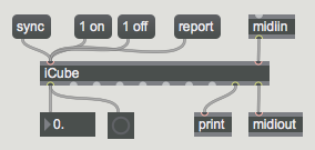
Commands can be sent while the digitizer is in host or standalone mode, with sensor data being output in either mode.
The command format has the general form "<outlet> <command> <value>", where <outlet> is a value between 0 and 32, and where <value> can be a float as well as an integer and is not required for all commands. If the outlet value is 0 it signifies the command applies system-wide, and not just for a specific input. All other values specified for <outlet> refer to the iCube outlet with the same number, ie. not the sensor input since the data outlet could have been connected to a sensor input with a different number. Multiple commands can be entered as one message, ie. without commas between each command. The outlet parameter "<outlet>" can be substituted by "<outlet1> - <outlet2>" to specify all outlets from <outlet1> to <outlet2>, which range can be ascending or descending.
If a command has aliases they are listed following the command, in brackets and separated by commas.
Commands that in turn send commands as System Exclusive MIDI messages to the digitizer refer to the firmware command in capitals. More information about the command can be found in the applicable firmware section on this support wiki.
For each command (sent or received) messages are output via the message outlet that provides confirmation or reports an error. These messages can be used for eg. debugging or the sequential timing of communication with the digitizer.
Arguments
iCube takes 4 optional arguments. Arguments are entered after the name "iCube" with spaces between each argument. If no arguments are given, the iCube object will default to 8 outlets (virtual outputs) and the MIDI System Exclusive Device ID will default to 0. The first argument indicates the number of outlets. If the first argument is not in the range [0..32] an error message will be shown in the Max window as well as output via the message outlet. The second argument indicates the MIDI System Exclusive Device ID (which must match the System Exclusive Device ID of a connected digitizer in order to work). If only one argument is provided or if the second argument is less than zero, the System Exclusive Device ID defaults to 0 and an error message will be shown in the Max window as well as output via the message outlet. The third argument (a string with at most 99 characters) can be used to identify messages from the iCube object instance in the Max window. It can be left empty by typing " " (a space with two double quotes). The fourth argument specifies the digitizer firmware (where eg. firmware v7.5 is entered as "75"). If no firmware is specified, iCube will assume default digitizer specs (maximum 32 inputs, maximum 12-bit resolution, minimum 0 ms sample interval and System Exclusive Device ID 0) and will try to identify the digitizer upon receipt of the first MIDI byte. See also the version command. If the fourth argument is -1 the iCube object will execute the sync command upon instantiation.
Instantiation
Upon instantiation, the oCube is initialized as follows:
System-wide:
- interval: 10 for firmwares greater than 5.1 and smaller than 6.0, greater than 6.2 and smaller than 7.0, or greater than 7.1, and 100 for other firmwares
- mute: 0, ie. off
- id: 0
- digid: 0
Input-specific:
- connect: each outlet is connected to the sensor input with the same number
- stream: 0, ie. off
- inmin: 0 (sensor input minimum voltage)
- inmax: 5 (sensor input maximum voltage)
- min: 0
- max: 5
- res: 1/1024 for all digitizers except the Digitizer, or 1/4096 for Digitizer
- steps: 1024 for all digitizers except the Digitizer, or 4096 for Digitizer
- noise: 1/(steps - 1) in host mode, or 0 in standalone mode
- smooth: 0
- unit: 5/(steps - 1)
- offset: 0
- preset: 1
- address: 0
- function: 0, ie. analog sensor with voltage output
- method: 0
