Difference between revisions of "EditorX Sensor Input Analog Digital"
| Line 4: | Line 4: | ||
==Analog / Digital== | ==Analog / Digital== | ||
| − | Sensors | + | Sensors output either analog or digital signals. Analog sensors output a single value that is captured by the digitizer using its analog to digital converter, after which a number of algorithms can be applied to process the sensor value and output it as a MIDI message. Digital sensors convert analog value(s) in the sensor itself and output a serial binary data stream using the I2C protocol that is received by the digitizer, which then can apply a number of algorithms to process the sensor values and output them as MIDI messages. |
When selecting Analog, a number of conversion methods will be made available that may be applied in conjunction with processing methods. When selecting Digital, a number of sensor presets can be selected, applicable to the corresponding I-CubeX sensors. | When selecting Analog, a number of conversion methods will be made available that may be applied in conjunction with processing methods. When selecting Digital, a number of sensor presets can be selected, applicable to the corresponding I-CubeX sensors. | ||
Revision as of 21:44, 9 November 2015
The Analog / Digital sub-section configures a sensor input for analog or digital sensors.
Analog / Digital
Sensors output either analog or digital signals. Analog sensors output a single value that is captured by the digitizer using its analog to digital converter, after which a number of algorithms can be applied to process the sensor value and output it as a MIDI message. Digital sensors convert analog value(s) in the sensor itself and output a serial binary data stream using the I2C protocol that is received by the digitizer, which then can apply a number of algorithms to process the sensor values and output them as MIDI messages.
When selecting Analog, a number of conversion methods will be made available that may be applied in conjunction with processing methods. When selecting Digital, a number of sensor presets can be selected, applicable to the corresponding I-CubeX sensors.
Analog Sensors
For analog sensors the following conversion methods are available:
- Thru
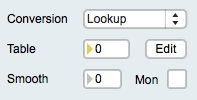
- Lookup table
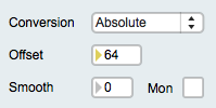
- Absolute value
- Time duration
- Frequency
- Absolute value + BPM
Please refer to the Firmware 7.2 FUNCTION command for more information about processing methods than provided here.
Thru
The thru function does not convert the sensor value but provides a way to smooth the signal and/or view it before processing it further. See also the THRU function.
Lookup table
A lookup table takes the sensor value as the index for a table and then outputs the value stored at that index. This method is useful for linearizing the response curve of a sensor, such as the ReachClose, ReachFar and all Touch sensors. See also the LOOKUP function.
Absolute value
The absolute value method subtracts an offset value of the sensor value and if the result is negative, changes the sign of the value so that the output is always positive.This method is useful for sensors whose value at rest, ie. when the sensor is not stimulated, is not zero but varies around a value, such as the BendMicro/Mini/Short, BioVolt and GForce3D. See also the ABSOLUTE function.
Time duration
The time duration method counts the milliseconds between a peak (or dip) and the following peak (or dip), if no Peak / Dip End notification processing method is enabled. If Peak / Dip End notification is enabled, the time duration method counts the time between a peak and its end (ie. the time the value drops below the threshold set for peak detection). The range of the time duration is 1 - 16383 ms. The time duration unit can be set separately, and setting it to 1 means the time duration is output in milliseconds, setting it to 100 means the time duration is output in 10ths of a second. This method has many applications, such as measuring the time between taps on a Touch sensor, the time a hand was held over a ReachClose sensor or the time between two activations of a MoveOn sensor. See also the TIME function.
Frequency
The frequency method operates like the time duration method but outputs a frequency instead of the time duration. The frequency unit can be set separately, and setting it to 1 means the frequency is output in Hertz (Hz), setting to 60 means the frequency is output as beats per minute (BPM). This method has many applications, such as measuring the BPM of taps on a Touch sensor, or the frequency of breaking a SeeLaser-Red beam pointed at a Flash sensor. See also the FREQUENCY function.
Absolute value + BPM
The "Absolute value + BPM" method combines the absolute method with the frequency method, as explained above, and optional smoothing (a smooth value of zero means it's disabled). The Mon button enables/disables the output of MIDI messages containing the sensor value after the absolute and smoothing (if enabled) methods are applied, but before conversion to beats per minute (BPM). This provides for a way to monitor the range of the sensor input values and adjust the offset value accordingly. This method is useful for capturing beats per minute (BPM) when using a BioVolt as a heartbeat sensor. See also the ABS-BPM function.
Digital Sensors
The following digital sensor presets are available:
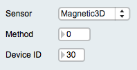
- Magnetic3D
- Moist
- MoveAlong
- MoveAround
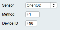
- Orient3D
Magnetic3D
See the MAGNETIC3D function for more information.
Moist
See the MOIST function for more information.
MoveAlong
See the MoveAlong function for more information.
MoveAround
See the MoveAround function for more information.
Orient3D
See the ORIENT3D function for more information.
Example:
- If the sensor is digital, eg. an Orient3D, the sensor's parameters are internally represented as virtual inputs numbered sequentially starting from the I2C port number, and all mapped to the same type of MIDI messages as set for the I2C port number but with their note or controller number, or MIDI channel (in the case of Pitchbend messages) incremented sequentially. For example, if the Orient3D is plugged into port 1 and configured to output as MIDI controller 10 messages, its heading value is internally represented as sensor input 1 and output as MIDI controller 10, its pitch value is internally represented as sensor input 2 and output as MIDI controller 11, and its roll value is internally represented as sensor input 3 and output as MIDI controller 12. Note that since the physical slot for sensor input 3 is not used by the Orient3D it's still possible to plug another sensor into it and output its values as another MIDI message.


