|
|
| Line 45: |
Line 45: |
| | *rpwidth: 0 ms | | *rpwidth: 0 ms |
| | *rpwidthinit: 0 ms | | *rpwidthinit: 0 ms |
| − |
| |
| − |
| |
| − |
| |
| − |
| |
| − | <b>Output-specific commands</b>
| |
| − |
| |
| − | Output-specific commands apply only to the specified inlet and the actuator output it is connected to, if any. Inlets and outputs are numbered starting with 1. The inlet parameter "<inlet>" can be substituted by "<inlet1> - <inlet2>" to specify all inlets from <inlet1> to <inlet2>, which range can be ascending or descending.
| |
| − |
| |
| − | Digitizer outputs can operate binary (ie. two-state) actuators, PWM (pulse width modulated) actuators and I2C actuators. Binary actuators are operated by the application of either 0 or 5 V, which then result in either of the two states of the binary actuator. PWM actuators are operated by the application of a repeating pulse of variable width, a special case of which are servos which are usually operated by applying a repeating pulse with an interval of 20 ms and a width between 1 - 2 ms. I2C actuators are operated by the exchange of pulse trains that represent a series of bytes as commands/messages.
| |
| − |
| |
| − | For a binary actuator "on" means the state corresponding to logic level "1", ie. when applying 5 V, and "off" means the state corresponding to logic level "0", ie. when applying 0 V. For an I2C actuator "on" and "off" mean the states that result from specific pulse trains that represent a series of bytes which the actuator interprets as "on" or "off" commands. The "on" and "off" definitions do not apply to PWM actuators.
| |
| − |
| |
| − | <u><inlet> connect <output></u> (<inlet> assign <output>)
| |
| − |
| |
| − | Connects the specified inlet to specified digitizer actuator output. Just like the inlet parameter "<inlet>" can be substituted by "<inlet1> - <inlet2>" to specify all inlets from <inlet1> to <inlet2>, which range can be ascending or descending, the output parameter "<output>" can be substituted by "<output1> - <output2>" to specify a range of outputs, which can also be ascending or descending. Example: "1 - 4 connect 4 - 1" connects inlets 1 thru 4 to outputs 4 thru 1, ie. inlet 1 is connected to output 4 etc.
| |
| − |
| |
| − |
| |
| − | <u><inlet> on <delay></u>
| |
| − |
| |
| − | Sends a SET OUTPUT command to the digitizer to turn a digital binary or I2C actuator connected to the output that's connected to the specified inlet on after the specified delay [0..long_max] in ms.
| |
| − |
| |
| − |
| |
| − | <u><inlet> off <delay></u>
| |
| − |
| |
| − | Sends a SET OUTPUT command to the digitizer to turn a digital binary or I2C actuator connected to the output that's connected to the specified inlet off after the specified delay [0..long_max] in ms.
| |
| − |
| |
| − |
| |
| − | <u><inlet> toggle <delay></u>
| |
| − |
| |
| − | Sends a SET OUTPUT command to the digitizer to switch the on/off status of a digital binary or I2C actuator connected to the output that's connected to the specified inlet after the specified delay [0..long_max] in ms.
| |
| − |
| |
| − |
| |
| − | <u><inlet> onoff <delay></u>
| |
| − |
| |
| − | Sends SET OUTPUT commands to the digitizer to immediately turn a digital binary or I2C actuator connected to the output that's connected to the specified inlet on and then to turn it off after the specified delay [0..long_max] in ms. If the actuator output is already on, it will be turned off after the specified delay.
| |
| − |
| |
| − |
| |
| − | <u><inlet> offon <delay></u>
| |
| − |
| |
| − | Sends SET OUTPUT commands to the digitizer to immediately turn a digital binary or I2C actuator connected to the output that's connected to the specified inlet off and then to turn it on after the specified delay [0..long_max] in milliseconds. If the actuator output is already off, it will be turned on after the specified delay.
| |
| − |
| |
| − |
| |
| − | <u><inlet> pulse <duration></u>
| |
| − |
| |
| − | Sends SET OUTPUT commands to the digitizer to immediately switch the on/off status of a digital binary or I2C actuator connected to the output that's connected to the specified inlet and then to switch the on/off status again after the specified duration [0..long_max] in milliseconds.
| |
| − |
| |
| − |
| |
| − | <u><inlet> level <value></u>
| |
| − |
| |
| − | Sends a SET OUTPUT command to the digitizer to set the actuator output connected to the specified inlet to the voltage level corresponding to the specified logic level value [0..1] ("0" corresponds to 0 V or "off", "1" corresponds to 5 V or "on").
| |
| − |
| |
| − |
| |
| − | <u><inlet> levelinit <value></u>
| |
| − |
| |
| − | Sends a SET OUTPUT INIT command to the digitizer to set the actuator output connected to the specified inlet to the voltage level corresponding to the specified logic level value [0..1] ("0" corresponds to 0 V or "off", "1" corresponds to 5 V or "on"), at power up, reset or upon execution of the init command.
| |
| − |
| |
| − |
| |
| − | <u><inlet> rp <status></u>
| |
| − |
| |
| − | Sends a SET OUTPUT command to the digitizer to set the actuator output connected to the specified inlet to the specified repeating pulse generation status [0..1] ("0" corresponds to "off", "1" corresponds to "on").
| |
| − |
| |
| − |
| |
| − | <u><inlet> rpinit <status></u>
| |
| − |
| |
| − | Sends a SET OUTPUT INIT command to the digitizer to set the actuator output connected to the specified inlet to the specified pulse generation status [0..1] ("0" corresponds to "off", "1" corresponds to "on"), at power up, reset or upon execution of the init command.
| |
| − |
| |
| − |
| |
| − | <u><inlet> rpwidth <width></u>
| |
| − |
| |
| − | Sends a SET OUTPUT command to the digitizer to set the actuator output connected to the specified inlet to output repeating pulses with the specified width [1..] in milliseconds.
| |
| − |
| |
| − |
| |
| − | <u><inlet> rpwidthinit <width></u>
| |
| − |
| |
| − | Sends a SET OUTPUT INIT command to the digitizer to set the actuator output connected to the specified inlet to output repeating pulses with the specified width [1..] in milliseconds, at power up or upon execution of the init command.
| |
| − |
| |
| − |
| |
| − | <u><inlet> address <value></u>
| |
| − |
| |
| − | Sends a FUNCTION command to the digitizer to set the I2C address of the digital actuator connected to the actuator output which in turn is connected to the specified inlet, to the specified value [0..127].
| |
| − |
| |
| − |
| |
| − | <u><inlet> function <value></u> (<inlet> func <value>)
| |
| − |
| |
| − | Sends a FUNCTION command to the digitizer to set the function number of the digital actuator connected to the actuator output which in turn is connected to the specified inlet, to the specified value [0..127].
| |
| − |
| |
| − |
| |
| − | <u><inlet> method <value></u>
| |
| − |
| |
| − | Sends a FUNCTION command to the digitizer to set the method number of the digital actuator connected to the actuator output which in turn is connected to the specified inlet, to the specified value [0..127].
| |
| − |
| |
| − |
| |
| − | <u><inlet> digital, feelvibe, seergb <value></u>
| |
| − |
| |
| − | Sends a FUNCTION command to the digitizer to set function number and (if applicable) the I2C address according to the type (as specified by the name of the command) of the actuator connected to the actuator output which in turn is connected to the specified inlet, and its method to the specified value [0..127]. The "digital" command covers binary and PWM (pulse width modulated) actuators and not actuators that use the I2C protocol. The method value is ignored in case of the "digital" command.
| |
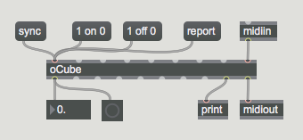
The oCube Max plugin responds to the commands listed below, sent to it using a Max message object.
Commands can be sent while the digitizer is in host or standalone mode, with sensor data being output in either mode.
The command format has the general form "<inlet> <command> <value>", where <inlet> is a value between 0 and 8, and where <value> can be a float as well as an integer and is not required for all commands. If the inlet value is 0 it signifies the command applies system-wide, and not only for a specific output. All other values specified for <inlet> refer to the oCube inlet with the same number. Multiple commands can be entered as one message, ie. without commas between each command. The inlet parameter "<inlet>" can be substituted by "<inlet1> - <inlet2>" to specify all inlets from <inlet1> to <inlet2>, which range can be ascending or descending.
If a command has aliases they are listed following the command, in brackets and separated by commas.
Commands that in turn send commands as System Exclusive MIDI messages to the digitizer refer to the firmware command in capitals. More information about the command can be found in the applicable firmware section on this support wiki.
For each command (sent or received) messages are output via the message outlet that provides confirmation or reports an error. These messages can be used for eg. debugging or the sequential timing of communication with the digitizer.
Commands may or may not be valid, according to the digitizer's firmware. An error message will be output if the command is not valid for the firmware of the connected digitizer.
Arguments
oCube takes 4 optional arguments. Arguments are entered after the name "oCube" with spaces between each argument. If no arguments are given, the oCube object will default to 8 inlets (virtual inputs) and the MIDI System Exclusive Device ID will default to 0. The first argument indicates the number of inlets. If the first argument is not in the range [0..8] an error message will be shown in the Max window as well as output via the message outlet. The second argument indicates the MIDI System Exclusive Device ID (which must match the System Exclusive Device ID of a connected digitizer in order to work). If only one argument is provided or if the second argument is less than zero, the System Exclusive Device ID defaults to 0 and an error message will be shown in the Max window as well as output via the message outlet. The third argument (a string with at most 99 characters) can be used to identify messages from the oCube object instance in the Max window. It can be left empty by typing " " (a space with two double quotes). The fourth argument specifies the digitizer firmware (where eg. firmware v7.5 is entered as "75"). If no firmware is specified, oCube will assume default digitizer specs (maximum 8 outputs and System Exclusive Device ID 0) and will try to identify the digitizer upon receipt of the first MIDI byte. See also the version command. If the fourth argument is -1 the oCube object will execute the sync command upon instantiation.
Instantiation
Upon instantiation, the oCube is initialized as follows:
System-wide:
- rpmode: 0 (general purpose repeating pulses, not servo-specific)
- rpinterval: 5 ms
- rpwidthmax: 1 ms
Output-specific:
- connect: connect each outlet to the sensor input with the same number
- address: 0
- function: 0, ie. digital actuator controlled by voltage level (0 or 5V) or repeating pulse width modulation
- method: 0
- level: 0 (off)
- levelinit: 0 (off)
- rp: 0 (off)
- rpinit: 0 (off)
- rpwidth: 0 ms
- rpwidthinit: 0 ms
