IoCube TD Plugin-12 Outputs
The Outputs parameter page allows you to configure each of the digitizer outputs.
Pulsing the Update button updates the actual status of each output.
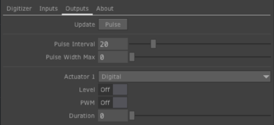
Pulse interval and maximum pulse width configure PWM (pulse width modulation) output of DC voltage binary "on/off" actuators. A pulse width maximum of 0 means that the pulse width varies between 1 and 2 ms. If the pulse interval is set to 20 ms and the pulse width maximum is set to 0 PWM output is suitable for control of common RC servos. When changing the pulse interval and/or pulse width max values, don't use the sliders but enter the value in the number field.
For each input, select the actuator (where "Digital" groups all DC binary actuators).
For Digital, ie. DC binary "on/off", actuators, switch the level to "on" or "off" or enable pulse width modulated (PWM) output and set the pulse width. To set the level and PWM status at power-on or reset, use the Reset interface of the actuator output section of EditorX.
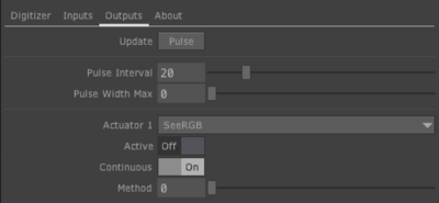
For I2C actuators, select the actuator's method (if the actuator communicates via I2C, see the SeeRGB example on the right below) and then activate it or enable continuous control to allow changing the method instantaneously in a continuous fashion. To set behaviour at power-on or reset, use the Reset interface of the actuator output section of EditorX. The "on" active status is set by enabling continuous control at power-on or reset and selecting the method as well as enabling the active status.
Actuator methods are algorithms that execute a sequence of events. See the functions section of the firmware that is running on the connected digitizer.

