This document will walk you through the procedure of connecting to the microDig using Max/MSP.
For this walkthrough, you will need:
Hardware
- A microDig
- Turn sensor (or any other sensor)
- A USB MIDI interface
Software
- A working installation of Max/MSP (v4.x or v5)
- iCube external in your Cycling '74/externals folder
- icubex.digitizer placed in the Max5/patches folder
Installing the iCube external
The iCube object talks to the microDig.
You can download it
here
Place the icube.mxo file (found in the objects folder within the zip file linked above) in
the folder Cycling '74/externals (Cycling '74/max-externals in Max5).
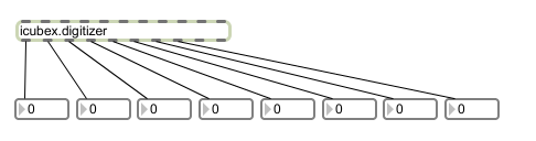
Using the icubex.digitizer object
Once the icubex.digitizer.maxpat file is placed in the Max5/patches folder, it can be integrated into your own patches. Alternately, if you choose not to put icubex.digitizer into the patches folder, you'll need to place it in the same folder as any patch that includes it.
The icubex.digitizer can be included in your patch, just like any object. Double-clicking on it brings up the patch itself, which has controls for connecting to the I-CubeX digitizer of your choice, and for turning sensor inputs on and off and changing the resolution of the sensor data. If you're using the microDig, you can also control the digital outputs from this patch.
Connecting to the microDig
Once you've added icubex.digitizer to your patch, double click on it to see the controls. In the Connection section at the top, choose microDig from the pulldown menu. You will then see a pulldown menu for the MIDI in port and one for the MIDI out port. Choose the appropriate input and output ports.
You should see both the in and out LEDs on the microDig blink
quickly and the port menus should both turn green. If they do not blink check that your MIDI interface is working and
that the cables are connected properly, particularly that the In/Out cables are each plugged into the right place.
Normally on MIDI hardware, "In" means "MIDI messages come in here" and "out" means "MIDI messages leave from here". On certain interfaces, this convention is not followed, which makes things confusing.
At this point, you can start receiving sensor data. To turn on any of the 8 analog sensor inputs, click on 1 of the 8 toggle
boxes. Next to each of the toggle boxes is a switch to choose between
low-resolution (7-bit) and high-resolution (10-bit). Note that on the left
hand side there is a toggle to turn all 8 inputs on or off, as well as a
resolution selector for all 8. The control for sampling interval control is immediately below the all-
input control. The minimum setting, corresponding to the maximum sampling rate, is 1 millisecond.
The sensor data is routed to the 8 outlets of icubex.digitizer, where it can be used by the rest of your patch.


 LinkedIn group