EditorX-82 I-O Mapping
The I-O Mapping section configures the values captured by the sensor inputs to be used for setting the actuator outputs.
To use sensor inputs to control actuator outputs, configure the sensor input, then select the same input (as well as virtual input, if working with a digital I2C sensor) in the I-O (input-output) mapping section and select the output you want to map to, then select the actuator behaviour, ie. whether to use threshold control (trigger or toggle logic), in the form of direct current (DC) signals (0 or 5 Volt), or continuous control (direct or inverse translation), in the form of pulse width modulation (PWM) of a 0-5V repeating pulse or I2C actuator method variation, and set the actuator output accordingly.
Output
Each sensor input can be used for controlling one actuator output. If the actuator output can support the connection of multiple similar actuator devices (check the actuator product page or ask us), one sensor input can control these actuators. Multiple inputs can be used for controlling the same actuator output but this may lead to erratic behaviour of the connected actuator if the sensor input values are within the mapped range.
The sensor input value can be mapped with up to 14-bit resolution depending on the actuator's resolution. The CVolt has 12-bit resolution, so if the sensor input is mapped to a 14-bit pitch-bend MIDI message the WiDig will internally map 12-bits of the pitch-bend message to the I-O map-enabled actuator output to which the CVolt is connected in the form of actuator method data.
Mode
The sensor input value can be used in 4 different ways to set an actuator output:
- Trigger
- Toggle
- Direct
- Inverse
Trigger
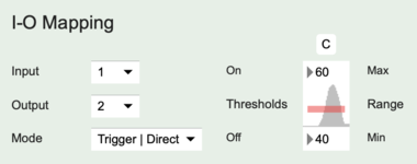
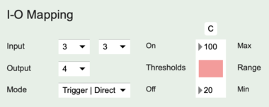
In Trigger mode the actuator output status changes from OFF to ON if the sensor input value is equal or greater than the ON value of the Threshold slider. The actuator output status is changed from ON to OFF if the sensor input value equal or less than the OFF value of the Threshold slider. By setting different values for the ON and OFF thresholds, rapid ON-OFF triggering, due to sensor input noise, can be avoided. Sending sensor input values continuously will also result in continuous evaluation of the triggering algorithm.
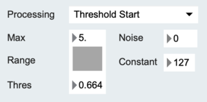
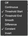
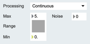
In the example below, using the Threshold Start feature, a MIDI message is output when the sensor input increases above the Thresh value displayed in the Processing section of the sensor input configuration. Using the Constant feature, the MIDI message's data byte is set to a constant value of 127, which is greater than the ON value of the Threshold slider in the I-O mapping configuration and hence the actuator output status will be switched to ON. Using the Threshold End feature, another MIDI message with data byte zero is output when the sensor input drops below the Thresh value. Since the data byte is zero it is less than the ON value of the Threshold slider, the actuator output status will be switched to OFF.
Now, changing the sensor input so that it crosses above and below the Thresh value multiple times will show as multiple lines indicating alternating high and low values in the example below. Each high value line represents the actuator being turned on and each low value line represents the actuator being turned off.
Toggle
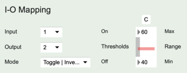
In Toggle mode the actuator output status changes from OFF to ON or from ON to OFF if the sensor input value is equal or greater the ON value of the Threshold slider. The sensor input value must decrease to be equal or less than the OFF value of the Threshold slider before the sensor input value can change the actuator output status again by becoming equal or greater than the ON value of the Threshold slider. Set the OFF threshold to zero to avoid rapid successive toggles due to sensor input noise. Sending sensor input values continuously will also result in continuous evaluation of the toggling algorithm.
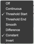
In the example below, using the Threshold Start feature, a MIDI message is output when the sensor input increases above the Thresh value displayed in the Processing section of the sensor input configuration. Using the Constant feature, the MIDI message's data byte is set to a constant value of 127, which is greater than the ON value of the Threshold slider in the I-O mapping configuration and hence the actuator output status will be switched.
Now, changing the sensor input so that it crosses above and below the Thresh value multiple times will show as the grey bar made of multiple lines indicating the same high value in the I-O mapping screen shot below. The lines represent the actuator being turned on or off in an alternating sequence, ie. ON OFF ON OFF etc.
If the Threshold End feature would be enabled, the actuator output status would also be switched when the sensor input value is equal or smaller than the OFF value of the Threshold slider in the I-O mapping configuration.
If the Threshold End feature is needed to generate a MIDI message but the actuator status should only be switched by a Threshold Start event, set the OFF value of the Threshold slider in the I-O mapping configuration to zero.
Direct/Inverse
In the Direct and Inverse modes sensor input is mapped continuously to an actuator output status. When Direct is selected and if the selected actuator output is set to CC mode the sensor input value is directly translated to the actuator method value. If it is set to PWM mode, the sensor input value is directly translated to the pulse width value.
The range of sensor input values that is used for the actuator method or pulse width is set by changing the Range Min and Max slider values.
The Inverse mode inverts the response, ie. when the sensor value increases the actuator method value or pulse width value decreases.
The Direct and Inverse modes can also be used with the actuator output set to DC mode but the sensor input will then be mapped to only the two ON and OFF actuator output values.
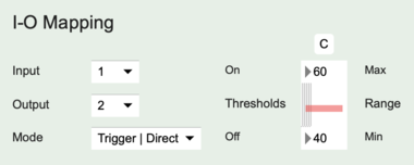
In the example below, the I-O mapping mode is set to Direct. When the sensor input's continuous change is within the 40 - 60 value range it results in a corresponding actuator output variation of either the actuator method if it uses I2C or of the pulse width if it uses PWM. A binary DC actuator will turn on once the MIDI message data value is equal or greater than 60 and it will turn off if the MIDI message data value is equal or less than 40.
If in the example below the I-O mapping mode is set to Inverse the actuator output (ie. actuator method or pulse width) will decrease when the sensor input value increases within the 40 - 60 range. Using a binary DC actuator will result in it trying to turn on and off as fast as the MIDI message value is sent if the MIDI message data value is equal or greater than 60 or equal or smaller than 40, while it will not switch status within the 40 - 60 value range.
If the Threshold End feature is needed to generate a MIDI message but the actuator status should only be switched by a Threshold Start event, set the OFF value of the Threshold slider in the I-O mapping configuration to zero.
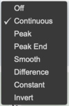
To map the roll parameter of an Orient3D connected to sensor input 3 to an RC servo connected to actuator output 4, select output 4 in the input-output mapping section of virtual input 3 of sensor input 3, then select Continuous and set the Range as desired.
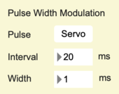
Actuator output 4 should be set to "PWM", ie. pulse width modulation and it should state "Servo" in the Pulse Width Modulation section. Note that the pulse width value is not updated in EditorX, although by clicking the "U" button (next to the Current/Reset button) it is possible to sample it and have it shown in the field below the button labeled "PWM".
CV Mapping
See the section on actuator outputs.

