IoCube TD Plugin-10 QuickStart USB-microDig
What you need
For this walkthrough, you will need:
- A USB-microDig (with hardware v7.5) and its drivers (see below).
- A Turn (or other) sensor for testing.
- Touchdesigner software.
- ioCube.
- SiliconLabs driver.
Installing the USB-microDig
On both Windows and MacOS, you'll first need to add the USB-microDig as a virtual serial (or COM) port by installing its SiliconLabs driver. If your operating system is not the most recent version, you may need to install an older driver.
On MacOS, the drivers were installed correctly if the connected USB-microDig is listed in System Report (under About this Mac), in the USB section under Hardware. There should be an entry "I-CubeX USB-microDig".
On Windows, the drivers were installed correctly if the USB-microDig is listed under ports in the Device Manager (select from the menu that appears after right-clicking on the Start menu) as a serial port with name "COM..".
On MacOS Sierra or higher, make sure to allow the driver extension in the "Security & Privacy" panel of the System Preferences, within 30 minutes after installation (or else re-install the drivers if MacOS doesn't show a way to allow the driver).
Connecting to the USB-microDig
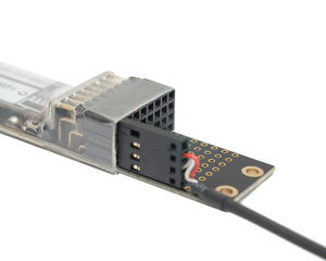
1. Connect the Turn sensor (or any other sensor) to input #1 of the USB-microDig as shown below, with the red wire on top and the black wire on the bottom.
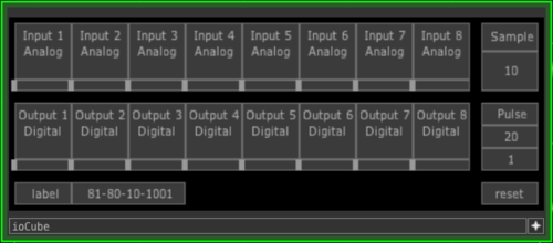
2. Start Touchdesigner. Drag and drop the ioCube.tox file into the project window. Enable "viewer active" by clicking the "+" icon in the bottom-right of the ioCube node.
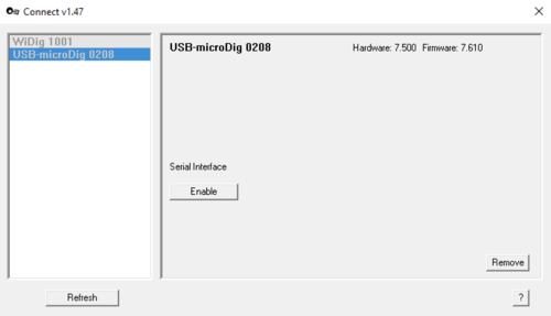
3. If you're running Connect, the digitizer you want to use with ioCube should be disabled in Connect. If it is enabled in Connect it'll prevent Touchdesigner from accessing the virtual serial port.
In the ioCube's parameter view's Digitizer page select the virtual serial (COM) port that is associated with the USB-microDig, and then enable "Activate". On MacOS the virtual serial port will be called "SLAB...". On Windows the COM port can be determined by checking the list of ports in the device manager.
4. In the node view click the "Input 1" button or in the parameter view's Inputs page enable the "Active" button of sensor 1 to turn on sampling of sensor input 1. In the node view the button will turn green and the sensor value will be shown as a number as well a slider.
5. You're up and running. For further details about using ioCube, refer to the ioCube help pages.


