EditorX-73 Actuator Outputs
The Actuator Outputs section configures the actuator outputs of the digitizer.
The actuator output section can display the currently active actuator output settings or the settings upon reset (eg. upon power-up). Click the button "Current" to switch to "Reset", and vice versa. You can also switch between the user interface for the configuration of MIDI System Exclusive control of actuator outputs (ie. directly via the EditorX user interface or via OSC messages that are automatically mapped to System Exclusive messages using the OSC window) or the user interface for the configuration of MIDI Channel Voice control of the actuator outputs (using eg. ControlChange messages). Click the button "SX" to switch to "CV" and vice versa.
Contents
Availability
On the Wi-microDig, if the port is used by a sensor, the menu of the actuator output with the same number is greyed out. Select one of the menu options to configure the port for actuator output (the sensor input will be greyed out and disabled instead). Note that an I2C device must be connected using a plug that occupies two slots of the Wi-microDig's input/output connector and hence that in EditorX the adjacent (next up) sensor input and actuator output are unavailable !
Actuator Type
Three actuator types can be controlled by the digitizer. Actuators such as a relay or an LED are binary, ie. they have two states, and are controlled by applying 0 or 5V DC. Other actuators such as an RC servo are controlled by applying a regular recurring pulse of varying width, ie. pulse width modulation (PWM). The SeeRGB and FeelVibe actuators are controlled by using a synchronous serial digital protocol called I2C, which involves exchanging pulse trains that represent bytes between the sensor and the digitizer.
Current/Reset
If the Current/Reset button is set to Current (pink color), the ON/OFF buttons set the current state. If the button is set to Reset (light blue color), the ON/OFF buttons set the state of the actuator outputs at power-up or after a software reset. If the actuator output is configured to be controlled by a sensor input (see the input-output mapping section) or by MIDI Channel Voice messages (see below), the status is not updated to reflect the current status effectuated by the digitizer. However, if the actuator output status is not rapidly changing it's possible to use the Update button to retrieve the current actuator output status.
Binary DC Ouput
Select "Digital" from the menu for the output and use the top ON/OFF button to set the state.
See also the SET OUTPUT, DUMP OUTPUT, the SET OUTPUT INIT, DUMP OUTPUT INIT commands.
Pulse Width Modulation
Select "Digital" from the menu for the output and use the bottom On/Off button to enable/disable PWM. The bottom row of ON/OFF buttons enables/disables pulse width modulation output, and changes the text on the ON/OFF buttons in the top row to PWM. The top row of ON/OFF buttons now only set the state that the actuator output should have after pulse width modulation is turned off.
The number fields below the bottom row of ON/OFF buttons set the pulse width in milliseconds. If its color is red it sets the current pulse width, if its blue it sets the pulse width at power-up or after a software reset. If the actuator output is configured to be controlled by a sensor input (see the input-output mapping section), the pulse width number field is not updated to reflect the current pulse width effectuated by the digitizer. However, if the actuator output status is not rapidly changing it's possible to use the Update button to retrieve the current actuator output status.
See also the SET OUTPUT, DUMP OUTPUT, the SET OUTPUT INIT, DUMP OUTPUT INIT commands.
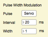
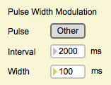
The Pulse Width Modulation section sets the pulse interval and the pulse width range which only can be configured for all actuator outputs at the same time. Increasing the pulse width range to at least half the interval is useful for dimming an LED such as the SeeGreen. The Servo button restores the pulse interval and pulse width range to default settings (a 1-2 ms wide pulse with 20 ms interval) for use with RC servos. RC servos need to be powered separately in order to operate, eg. by using the 5V from a USB port via a USB cable. An AuxCable can be modified to provide the necessary wiring to connect to the USB-microDig, or a cable can be made using HackPlugs.
See also the SET OUTPUT PULSE, DUMP OUTPUT PULSE commands.
I2C Actuators
The following I2C actuator presets are available:
- FeelVibe
- SeeRGB
FeelVibe
See the FEELVIBE function for more information.
SeeRGB
See the SEERGB function for more information.
Select "SeeRGB" or "FeelVibe" from the actuator type menu to control these I2C actuators, use the top ON/OFF button to set the state and the number box to select the actuator method.
Control With MIDI Channel Voice Messages
The CV user interface configures the actuator outputs to respond to MIDI channel voice messages (eg. ControlChange messages) sent to the digitizer. The response mode can be set with the bottom row of TRIG/TOG buttons.
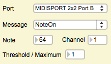
The MIDI Input section sets the parameters for receiving MIDI Channel Voice messages. The Port menu lists the available MIDI ports. The Message menu lists the available MIDI messages (NoteOff, NoteOn, KeyPressure, ControlChange). The Control or Note field sets the control or note number for actuator output 1. The Thresh/Max value sets the threshold above which an actuator output is triggered or toggled (depending on the mode of the actuator output), or, if the actuator output is in continuous mode (ie. using pulse width modulation), it sets the maximum value of the MIDI message to be used for setting the pulse width. In the latter case the pulse width is scaled between the minimum pulse width and the pulse width represented by Max, and the response is inverted if the actuator output is in toggle mode.


