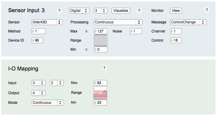
EditorX-73 I-O Mapping
The I-O Mapping section configures the values captured by the sensor inputs to be used for setting the actuator outputs.
To use sensor inputs to control actuator outputs, configure the sensor input, then select the same input in the input-output mapping section and select the output you want to map to, then select the actuator behaviour, ie. whether to use on/off (Trigger and Toggle) or pulse width modulation (PWM) control and set the actuator output accordingly.
Note that it's possible to map multiple sensor inputs to the same actuator output. However, the actuator output may behave unpredictably if the sensor input values are both within the mapped range.
Output
Each sensor input can be used for setting one actuator output. Multiple inputs can be used for setting the same actuator output but this may lead to erratic behaviour of the actuator.
Mode
The sensor input value can be used in 3 different ways to set an actuator output:
- Trigger
- Toggle
- Continuous
Trigger
The Trigger mode changes the actuator output state from off to on if the sensor input value reaches the On value of the Threshold slider. The actuator output state is changed from on to off if the sensor input value reaches the Off value. By setting different values for the On and Off threshold rapid on-off triggering, due to sensor input noise, can be avoided.
Toggle
The Toggle mode changes the actuator output state from off to on and vice versa if the sensor input value reaches the On or Off value of the Threshold slider. Set the Off threshold to zero to avoid rapid successive toggles due to sensor input noise.
Continuous
The Continuous mode sets the selected actuator output to Pulse mode, ie. the output changes state rapidly so that pulses form of which the width is set by the sensor input value. The range of sensor input values that is used for the pulse width is set by changing the Range Min and Max slider values. The Continuous Inverted mode inverts the response, ie. when the sensor value increases the actuator control value decreases. This mode is not applicable to I2C actuators.
For example, to map the roll parameter of an Orient3D connected to sensor input 3 to an RC servo connected to actuator output 4, select output 4 in the input-output mapping section of virtual input 3 of sensor input 3, then select Continuous (the actuator output 4 should automatically display "PWM", to show it is set to pulse width modulation) and set the Range as desired.


