This document explains how to connect the Wi-microDig and get sensor data into your computer using Link. It also describes how Link can be used to process the signal coming from the sensor, and send out messages via MIDI or OSC (OpenSoundControl).
What you need
For this walkthrough, you will need:
- A Wi-microDig.
- Bluetooth adapter (likely built in to your computer if it's a Mac).
- A Turn (or other) sensor for testing.
- Link software, available here.
Getting started
Adding the Wi-microDig as a Bluetooth device
In both Windows and Mac OS X, you'll first need to add the Wi-microDig as a virtual serial port. The instructions
here explain how to do this. Once this is done, you can continue to the next section.
Connecting to the Wi-microDig
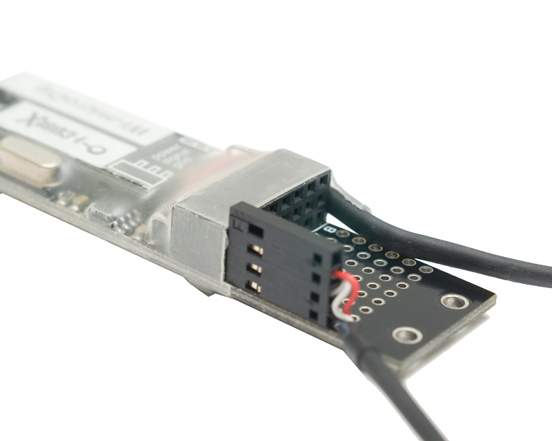
Connect the Turn sensor (or any other sensor) to input #1 of the
Wi-microDig.
Make sure the sensor is connected as shown below, with the red wire on top
and the black wire on the bottom.
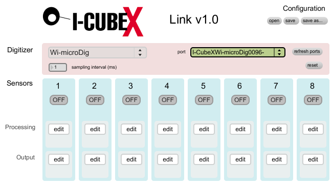
Launch Link.
In the Connection section at the top, choose Wi-microDig from the pulldown menu.
On MacOS, from the adjacent pulldown menu, select your Wi-microDig indicated by its serial number. On Windows, from the adjacent pulldown menu, select your Wi-microDig as per the corresponding COM port that was created during the "add Bluetooth device" procedure for your Wi-microDig.
If you don't see the wi-microDig listed, make sure
you've added it as a Bluetooth device following the instructions above.
Upon connecting, the port menu will turn green and the blue LED on the Wi-microDig will illuminate.
If the patch doesn't connect to the Wi-microDig, check that your
Bluetooth is turned on. Link will not warn you if it is turned off, it
will just not connect.
Processing
The processing window shows the flow of the sensor data, moving from left to right. This left-to-right order represents the order of how each block is applied to the sensor signal. By default Absolute Value and Peak / Dip are inactive.
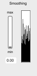
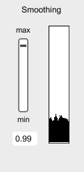
Smoothing
This applies exponential smoothing to the signal. Use this when you want to ignore small changes from a particularly noisy sensor. It's often useful in conjunction with Peak to avoid having small changes acting as a false trigger.
In the pictures below, you can see the raw signal on the left and the smoothed signal on the right. Notice the lack of sharp peaks.
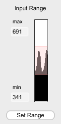
Input Range
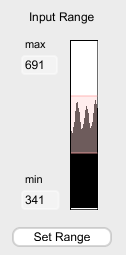
You can use this to "zoom in" on the signal for a particular range. For example, if a particular sensor outputs a signal between 341 and 691 (roughly 1.7 and 3.3 Volts) and you would like that to correspond to the entire range, set the max to 691 and and min to 341. The input range block will then scale the signal such that 691 now corresponds to 1023 and 341 corresponds to 0.
You can also set the range by clicking on the Set Range button and then using the sensor so that it hits the minimum and maximum values. When you click Done, the highest and lowest points hit by the signal will be set to the min and max
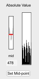
Absolute Value
This block is useful for sensors that have a signal that increases and decreases around a non-zero rest value. Examples include the GForce family of sensors and the Push2D amongst others. Once you set a midpoint, using either the sliders/number-box or the Set Mid-point button, the midpoint will be set to the new zero point and then any signal below or above the mid-point will be added to zero. This block can then be used to measure the overall magnitude of a signal while disregarding the direction.
Peak/Dip
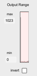
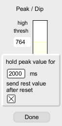
This block filters the signal and only sends the peak value above a certain threshold. In other words, once the signal increases above the threshold, as soon as the signal stops increasing the peak value is sent. No other values will be sent until the signal drops back down below the threshold. In the image below, the peak value can be seen as a narrow blue band in the Peak/Dip block, as well as a spike in the Output range block. Dip is the same as Peak, but with the direction reversed, i.e. the dip refers to the lowest point after the signal has dropped below the lower threshold. Both thresholds can be set using either the number boxes, or by dragging the yellow region on top of the signal view.
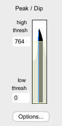
There are two optional parameters associated with Peak/Dip. One is the hold time, during which all further input to the block is ignored. In the image below, the hold time is set to 2000 ms, or 2 seconds. In this example, after the peak value is output the hold timer starts and nothing will be output until the 2 seconds have passed.
The other option is to send a reset value when the signal crosses back below the threshold. This is useful in conjunction with MIDI Note On messages to end a note started by a peak value. For Peak, the reset value is 0 and for Dip the reset value is 1023.
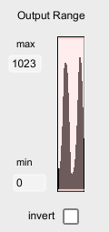
Output Range
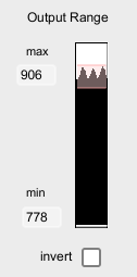
This block scales the signal range down to whatever range you set using the sliders or number boxes. For example, if you would like to limit the range of the signal to a value between 778 and 906, you would use the Output Range block to do this.
Output
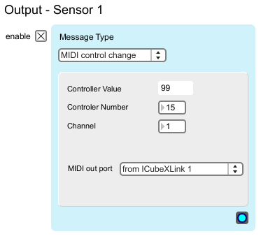
MIDI Control Change
This block outputs Control Change messages. The processed sensor signal is set to the controller value, leaving the controller number, MIDI Channel and MIDI out port to be set. Note that since the value can only be between 0 and 127, the signal coming in is scaled from 0-1023 to 0-127.
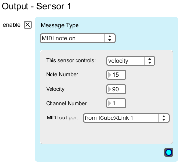
MIDI Note On
This block outputs a MIDI Note On message. The processed sensor signal can be set to control either the note number, or the note velocity. You can also set the MIDI Channel number as well as the MIDI out port. As with Control Change, the signal is scaled from 0-1023 to 0-127.
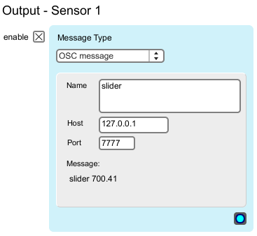
OSC Message
This block sends out an OSC message using the processed sensor signal. You can specify the the text portion of the message, including slashes. You can also set the Host IP and Port for the recipient of the OSC messages. Note that putting multiple text strings separated by spaces causes multiple messages to be sent with different names but the same numerical value.


 LinkedIn group