This document will walk you through the procedure of installing the drivers and connecting to your USB-microDig using Max/MSP. For the older version of the plugin, see here.
For this walkthrough, you will need:
Hardware
- A USB-microDig.
- Turn sensor (or any other sensor).
Software
- A working installation of Max/MSP.
- Virtual Serial Port driver.
- Connect.
- iCube external in your Cycling74/externals folder.
- icubex.digitizer placed in the Max/patches folder.
Installing the Virtual Serial Port driver
The USB-microDig requires a driver to allow it to be recognized and represented by the operating system as a virtual
serial port. You can find the driver
here.
You may need to reboot after installing the drivers.
Installing the Connect application
Connect can be found
here.
Installing the iCube external
The iCube object talks to the USB-microDig.
You can download it
here.
Place the icube.mxo file (found in the objects folder within the zip file linked above) in
the folder Cycling74/externals (Cycling74/max-externals in Max).
Using Connect to create a MIDI port for your USB-microDig
As of version 2.0, all Bluetooth and USB connectivity is handled by Connect. It runs in the background and creates a virtual MIDI port to communicate with the USB-microDig. Simply plugging in the USB-microDig causes the virtual MIDI port to be created with the name and serial number of the USB-microDig.
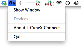
Open Connect. It will appear as a menu item at the top of the screen.
-
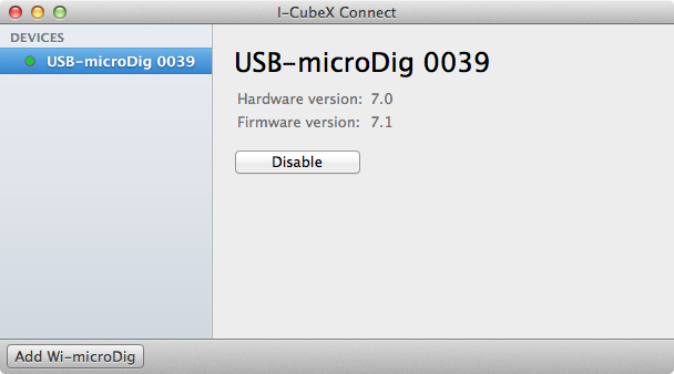
Connect the USB-microDig to your Mac. It should appear in the list of devices. A virtual MIDI port named USB-microDig XXXX will be created, with XXXX being the serial number. The red LED on the USB-microDig will also stop flashing.
If it doesn't appear, make sure your kernel extension (ie driver) is installed.
It should be in the following location: /System/Library/Extensions/SLAB_USBtoUART.kext
Using the icubex.digitizer object
Once the icubex.digitizer.maxpat file is placed in the Max5/patches folder, it can be integrated into your own patches. Alternately, if you choose not to put icubex.digitizer into the patches folder, you'll need to place it in the same folder as any patch that includes it.
The icubex.digitizer can be included in your patch, just like any object. Double-clicking on it brings up the patch itself, which has controls for connecting to the I-CubeX digitizer of your choice, and for turning sensor inputs on and off and changing the resolution of the sensor data. If you're using the USB-microDig, you can also control the digital outputs from this patch.
Connecting to the USB-microDig
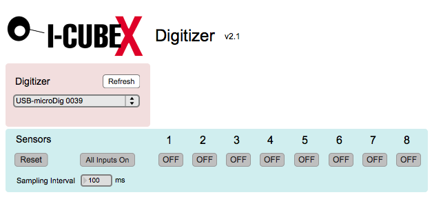
Once you've added icubex.digitizer to your patch, double click on it to see the controls. In the Digitizer section, select the USB-microDig from the pull down menu.
If you don't see the port listed, make sure
your driver is properly installed.
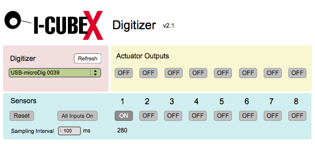
Upon connecting, the port menu will turn green and the red LED on the USB-microDig will stop flashing. At this point, you can start receiving sensor data. To turn on any of the 8 analog sensor inputs, click on the "on/off" button associated with that input.
The control for sampling interval control is immediately below the all-
input control. The minimum setting, corresponding to the maximum sampling rate, is 1 millisecond.
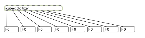
The sensor data is routed to the 8 outlets of icubex.digitizer, where it can be used by the rest of your patch. You can also include the plugin in a bpatcher. This and more is further explained in icubex.digitizer.maxhelp, which is included with the patch.
Digital Outputs
The USB-microDig has 8 digital outputs that can be set to either 0 or 5
volts. You can turn them off and on by using the digital output toggles.


 LinkedIn group